Welcome to the Electronic Supplies by Industrial Electronics By Ross LLC

Industrial Electronics By Ross LLC |
|

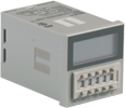
Time Delay Relays
Time Ranger™ III Digital-Set Multi-Function Multi-Range
|
|


Single Function Units
| FUNCTION | INPUT VOLTAGE | PRODUCT NUMBER | WIRING/SOCKETS | |||
| 8 FIELD- SELECTABLE FUNCTIONS |
12-240VAC 50-60Hz & 12-240VDC |
9816U1 | DIAGRAMS 7, 8 or 9 11 Pin Octal (see below) |
|||
Click here for Sockets & Accessories. | ||||||
Application Data | |
|
Voltage Tolerance Repeat Accuracy Setting Accuracy Recycle Time: |
Temperature: Output Contacts: Life: Approvals: |
Sockets & Accessories
| DESCRIPTION PRODUCT | NUMBER |
| 11 Pin Octal Socket (Surface or Track Mounting) | 70170-D |
| 11 Pin Octal Socket (Back-Mounted) | 70300 |
| Panel Mounting Adaptor | 70310 |
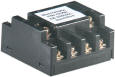 70300 11 Pin Octal Socket (Back-Mounted) |  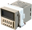 70310 Panel Mounting Adaptor |
 70320 Protective Cover |
Dimensions
 | 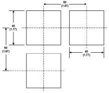 Panel CutoutAll Dimensions in mm (in) |
Description of Functions
| Function | Operation | ||
| MODE A | On Delay | Standard (Diagram 7) |
Upon application of control power, the preset time begins. At the end of the preset time, the relay contacts transfer. Control power must be removed and reapplied to reset the time delay relay. |
| Triggered (Diagram 9) |
Upon application of control power, the time delay relay is ready to accept trigger signals. Upon closure of the Start switch, the preset time begins. At the end of the preset time, the relay contacts transfer. Any closure of the Start switch is ignored until reset. The time delay relay is reset by closing the Reset switch or removing the control power. | ||
| MODE B | Flasher | Standard (Diagram 7) |
Upon application of control power, the preset time begins. At the end of the preset time, the relay contacts transfer and remain in that condition for the preset time. At the end of this time, the relay contacts return to their normal condition and the sequence repeats until control power is removed. |
| Triggered (Diagram 9) |
Upon application of control power, the time delay relay is ready to accept trigger signals. Upon closure of the Start switch, the preset time begins. At the end of the preset time, the relay contacts transfer and remain in that condition for the preset time. At the end of this time, the relay contacts return to their normal condition and the sequence repeats until the Reset switch is closed or control power is removed. | ||
| MODE C | Interval/ Off Delay |
(Diagram 8) | Upon application of control power, the time delay relay is ready to accept trigger signals. Upon closure or opening of the Start switch, the relay contacts transfer and the preset time begins. At the end of the preset time, the relay contacts return to their normal condition. Any closure or opening of the Start switch during timing causes the time to reset. |
| MODE D | Off Delay (I) | (Diagram 8) | Upon application of control power, the time delay relay is ready to accept trigger signals. Upon closure of the Start switch, the relay contacts transfer and hold. Upon release of the Start switch, the preset time begins. At the end of the preset time, the relay contacts return to their normal condition. Any application of the Start switch will reset the time. |
| MODE E | Interval On | Standard (Diagram 7) |
Upon application of control power, the relay contacts transfer and the preset time begins. At the end of the preset time, the contacts return to their normal condition. Control power must be removed and reapplied to reset the time delay relay. |
| Triggered (Diagram 9) |
Upon application of control power, the time delay relay is ready to accept trigger signals. Upon closure of the Start switch, the relay contacts transfer and the preset time begins. At the end of the preset time, the contacts return to their normal condition. Any closure of the Start switch is ignored until reset. The time delay relay is reset by closing the Reset switch or removing the control power. | ||
| MODE F | Delayed Interval |
Standard (Diagram 7) |
Upon application of control power, the preset time begins. At the end of the preset time, the relay contacts transfer and remain in that condition for the preset time. At the end of this time, the relay contacts return to their normal condition and the sequence stops. Power must be removed and reapplied to reset the time delay relay. |
| Triggered (Diagram 9) |
Upon application of control power, the time delay relay is ready to accept trigger signals. At the end of the preset time, the relay contacts transfer and remain in that condition for the preset time. At the end of this time, the relay contacts return to their normal condition and the sequence stops. Power must be removed and reapplied to reset the time delay relay. | ||
| MODE D | On Delay/ Off Delay |
(Diagram 8) | Upon application of control power, the time delay relay is ready to accept trigger signals. Upon closure of the Start switch, the preset time begins. At the end of the preset time, the relay contacts will transfer. Upon opening of the Start switch, the preset time begins. At the end of the preset time, the output contacts return to their normal condition. |
| MODE D | Off Delay (II) | (Diagram 8) | Upon application of control power, the time delay relay is ready to accept trigger signals. Closure of the Start switch is ignored. Upon release of the Start switch, the relay contacts transfer and the preset time begins. At the end of the preset time, the relay contacts return to their normal condition. Opening the Start switch during timing resets the time. |
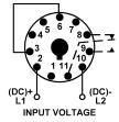 DIAGRAM 7 |
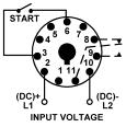 DIAGRAM 8 | 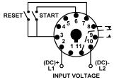 DIAGRAM 9 |
| Catalog, Quote, Availability. Call: 414-327-1555 ,Fax : 414-327-0577 , Email: indelect@execpc.com |
©1995-2006 Industrial Electronics By Ross LLC ©2003-2006 SEO by synscon.com Search Engine Marketing Company |